
Different fuel sender units
and testing methods
The early models are equipped with an electronic sender
unit.
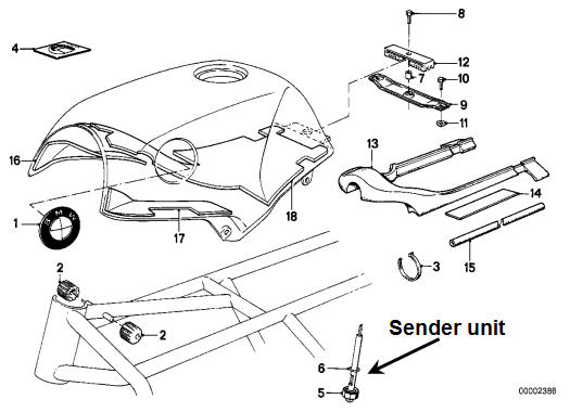
There are two thermistors housed in the fuel sender unit which is
located in the fuel tank. The thermistors are positioned at two
different levels corresponding to 7 and 4 litres.
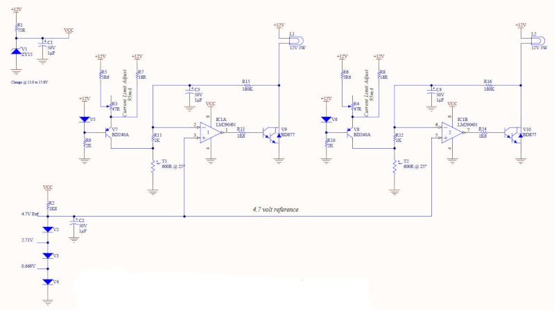
When the thermistor is
exposed to the air in the tank the appropriate light is illuminated.
Each thermistor is supplied with 12 volts that is current limited to
95mA, this current limit is controlled by the BD240A's and there
accompanying circuitry.
With the applied voltage the thermistors self
heat, when they are immersed in fuel the heat is dissipated and the
resistance is approximately 600 ohms.
While the thermistor is immersed
in fuel the inverting input of the op-amp has 12 volts applied to it.
This voltage level is above the 4.7 volt reference applied to the
non-inverting input of the op-amp and thus the output of the op-amp is
below the 0.7 volts needed to turn on the NPN transistor (BD877) which
controls the lamp. When the thermistor is above the fuel level and in
air, the self heating causes its resistance to drop below 53 ohms, the
voltage at the inverting input of the op-amp drops with it to below the
4.7 volt reference level applied to the non-inverting input of the
op-amp. This causes the output of the op-amp to swing to its maximum
positive level (+12V).
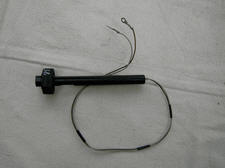
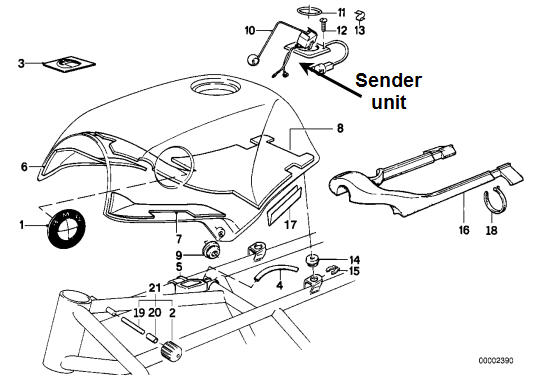
The latest K bikes fuel sender unit
can accommodate the installation of a fuel level gauge
 Testing
the float arm sender Unit
(by RobMack)
Testing
the float arm sender Unit
(by RobMack)
I had a chance to look at my failing
fuel level sender today and discovered information that would be useful
for the community.
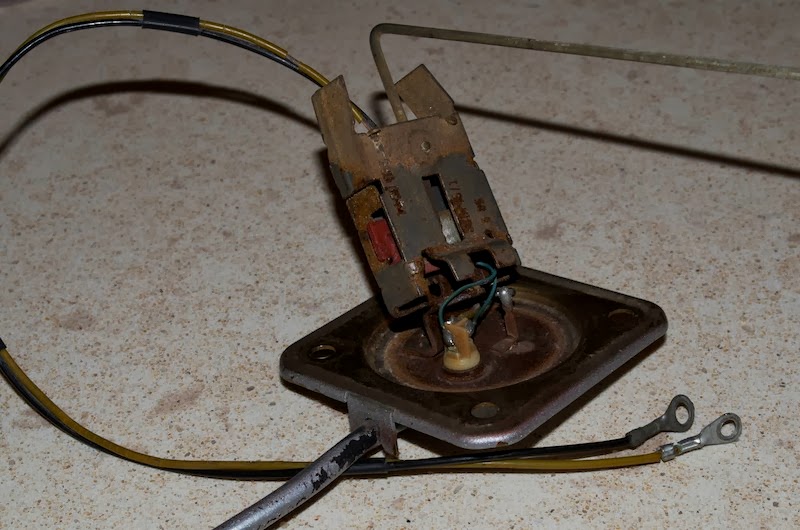
How does it work:
The sender has a movable arm ending in a float that
raises and lowers according to the fuel level. The arm articulates a
pair of metal wipers over two circuit cards.
The assembly is housed in a metal box welded to a bracket that mounts to
the bottom of the tank. The wiring goes through a liquid-tight
connector assembly.
Fuel Level Sensing:
The upper wiper sweeps across a 130 ohm wire wound
resistor plate, one end of which is connected to the liquid-tight
connector and the other end is not connected to anything.
The lower wiper sweeps across another plate containing two circular
contacts, one of which is wired to the liquid-tight connector, the other
is not connected at all.
The upper wiper outputs a resistance value between 2 and 130 ohms,
proportional to the position of the wiper.
When the tank is full of fuel, the float is in its highest position and
the resistance measured should be around 2 ohms.
When the tank is nearly empty, the float is at its lowest position and
the resistance measured should be around 130 ohms.
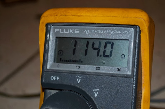
To test the resistive wire, use a multimeter with
resistance measuring capability.
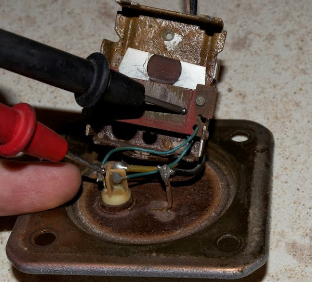
As in the photo set below, when measuring between the connector and the
left side of the resistor, the value should be around 130 ohms.
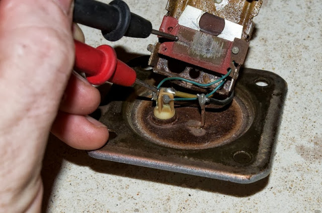
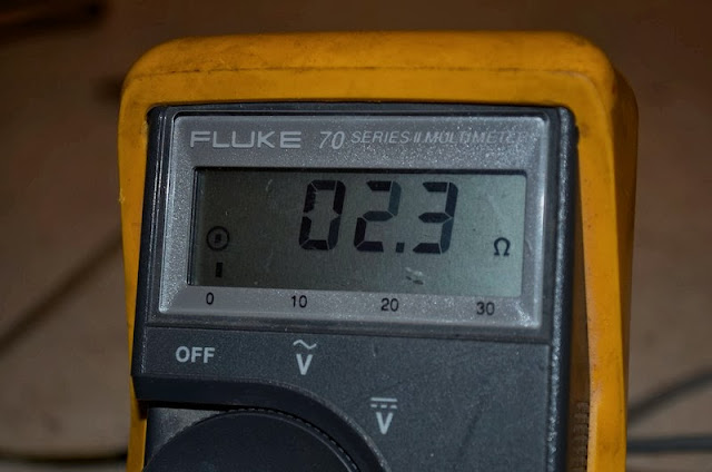
When measuring between the connector and right side of the resistor, the value should be around 2 ohms.
Reserve level Sensing:
The lower wiper outputs a binary signal
-- open circuit or grounded -- that communicates the reserve volume to
the low fuel light on the instrument cluster.
Normally, when the tank is full of fuel, the circuit is open. When the
arm reaches a certain position, the wiper contacts the conductor and the
output gets grounded.
This signals when the float reached the reserve position and the
instrument light should illuminate.
To test, , use a multimeter with resistance measuring capability. As in
the photo set below, there should be conductivity between the connector
and the left side plate.
There should be no conductivity between that same conductor and the right side plate.

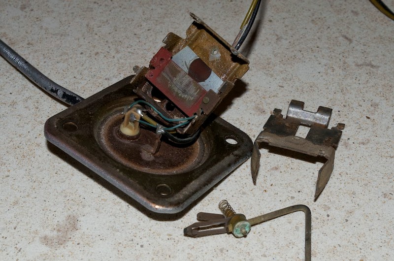
How to Recondition the Sender:
The sender tends to fail because years
of accumulated corrosion prevents conductivity. The symptom of corrosion
will be erratic resistance readings from the upper wiper.
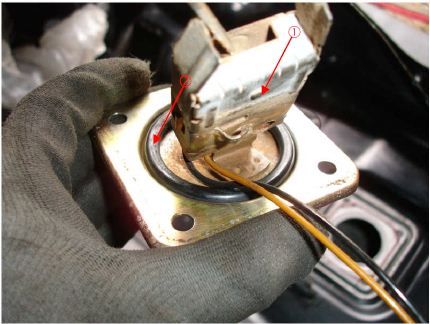
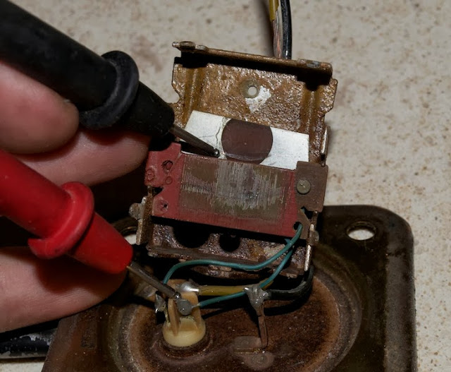
In the photo below, note the thick brown corrosion on the pivot hole and
green corrosion on the float arm pivot.
All this corrosion prevents an accurate resistance measure being sent to
the fuel gauge.
To recondition a failing sender, it is necessary to open the metal box
and clean the contacts.
There are four tabs that hold the case
closed. Carefully bend the tabs straight and the top will separate.
Be careful because there is a spring under the wiper arm and it may
fly off.
Remove the wiper arm and check that the contact pads look clean and shiny.
Depending on the age of the sender and
other factors, it may take no more than some Deoxit cleaner and a cotton
swab to clean the corrosion from the wires.
I would try this first. If the Deoxit doesn't get rid of the
accumulated corrosion, resort to a mildly abrasive paper.
Using a small piece of 1200 grit wet and dry sandpaper, carefully clean
the resistive wires of accumulated corrosion.
The technique is to fold a tiny piece in half so that is has some
stiffness and careful drag it across the wires IN THE SAME DIRECTION
AS THE WIRES ARE WOUND.
I use emphasis because you don't want to drag the abrasive paper across
the wires as it may break them.
Don't use any more pressure than is offered by the stiffness of the
sandpaper, such as pressing with your finger. The wire used is very
brittle and can easily break.
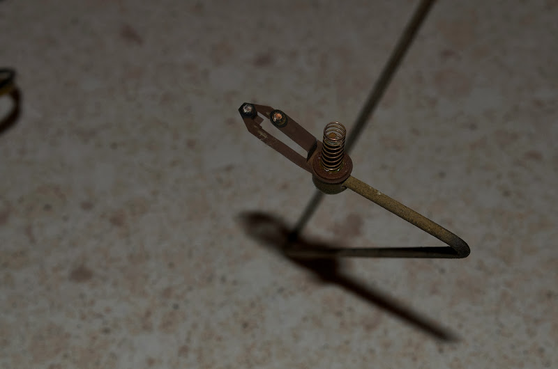
Using the same 1200 grit wet and dry, clean in and around both pivot
holes as well as the float arm pivots.
It is important to clean all corrosion from the pivots as from the hub
where the wiper blades are fixed.
The spring is there to act as a conductor, to allow electricity to flow
through the wipers, through the spring, through the pivots to ground.
This is the critical area where corrosion buildup will break the
sender. Once all corrosion is removed, reassemble the parts.
Test whether the cleaning is successful
by measuring the resistance over the entire sweep of the float arm.
The ohm meter should read consistent increasing resistance as the arm
moves from full limit to empty limit.
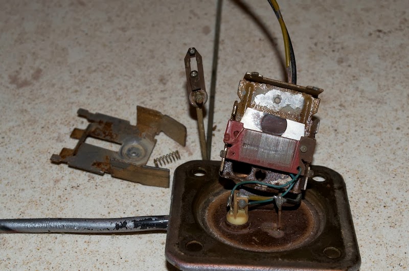
Reserve Level Adjusting
The point where the low fuel light
illuminates is dependent on the point during the rotation of the lower
wiper when it encounters the contact plate.
There is an adjustment on the sender which can determine when the lower
wiper contacts the plate.

In the photo above, you can see a
toothed wheel. This wheel rotates on a nylon pivot, causing the bottom
plate to be rotated and the contact to change position.
Using a small screwdriver, get a purchase on either of the indicated
lever points and engage the tip of the screwdriver's blade with one of
the teeth of the wheel.
Rotate the wheel with a levering
action.
* Rotating the wheel CLOCKWISE will cause the wiper to contact earlier,
resulting in a LARGER reserve volume.
*Rotating the wheel COUNTER CLOCKWISE will cause the wiper to contact
later, resulting in a SMALLER reserve volume.