|
BMW KBike Speedo Repair Page 1 by Jim Davis |
||||||
|
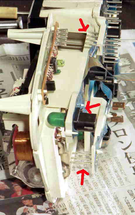
First of all, for disassembly of the instrument housing, I refer you to the IBMWR Ktech page: http://www.ibmwr.org/ktech.shtml- Read through all their faqs about speedo problems. You must first do some testing to decide if the problem is inside the instrument housing, or in the sensor on the final drive, or in the wiring and connections between it and the instrument housing. If some tapping on the housing while riding makes the instruments work or not work, you know the problem is likely in the instrument housing or the main plug onto it. If no change is noted with some tapping on the housing, you should check the speedo sensor on the final drive, and the wiring and connections from it. Check the sensor wire connector under the seat right side, and clean the pins on, then reseat the main connector on the instrument housing. The rear sensor can be removed and cleaned. After all these things fail to get the instruments working properly, you will have to remove and open up the instrument housing. It's not a bad idea to do so anyway, as the internal plug-in pins can cause many problems if they've not been cleaned in awhile. It's quite easy to remove and disassemble the unit, but the tricky part is separating the speedo unit from the main board. The following photos may help in doing this. The first time I went into the instrument housing, my trip meter had stopped working, so I decided to take it apart and see what the problem was. It turned out that I had a couple of loose screws and it was easy to fix. There are a couple of key things to know when doing any repair on this instrument. To separate the speedo from the main circuit board, you need to separate it as you see below in the first photo. |
||||||
|
Note: These pins should be cleaned up in order to ensure good electrical contacts. I sanded the pins lightly with very fine sandpaper and worked them in their sockets a few times. Once the board is separated, you can examine it for any problems. The light bulbs are the small bayonet type, and have a flexible green plastic cover on them. A suggestion to get red instrument lighting is to remove the green covers and paint the bulbs with red nail polish. You can also purchase all sorts of fancy coloured bulbs that will fit. I'm actually a bit intrigued about red instrument lighting, and might paint my bulbs in the future. You can also just remove the green covers and get brighter white lighting.
My previous K100RS bike came with red instruments. Check them out, cool eh?
Below,
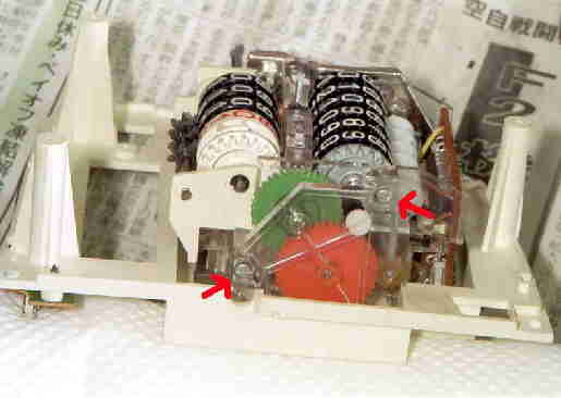
shown by red arrows, are screws that hold the clear plastic end of the
wheel case on. To the right of the yellow wheel in the bottom right corner is the speedo adjusting pot that some people have used to adjust their speedo accuracy. I have found my speedo to be quite accurate, but yours may read too high as many do. See the IBMWR faqs for adjustment of this pot. In order to determine the problem that your unit has, you may have to take the speedo needle off to get the speedo's face off. I pried very carefully but forcefully with two small screwdrivers on each side of the needle, using a piece of stiff paper under them to keep from marring the face. It will come off, be brave. However, you may not have to remove the needle and face, and I recommend you do not unless you have to. For the problem that I had, it turned out that I didn't have to remove the face, but I had to figure out how the trip meter was activated in order to find and fix the problem. Check the wheels for excessive play or sideways movement. If your speedo has been working erratically, I would suggest cleaning all the contact pins and trying it.
Below
is a view of the speedo unit itself. You can see the speedo needle
shaft in the center. At least you will be able to get the unit apart now, hopefully without breaking anything important. This unit is fairly robust, but be careful of the flexible flat ribbon cables that flop out of the mechanism in places. Follow Up - After checking my speedo and tightening up the screws mentioned, my trip meter started working perfectly. Unfortunately a few hundred miles later, my speedo started working erratically. A slight tap on the housing started it working again. This told me that connections inside the housing were definitely the problem. So, cleaned up all the connection pins of the main plug, and I went back into the unit and cleaned the connection pins on the speedo board. I lightly sanded all the pins, and worked them in their sockets a few times. Even though the pins looked very clean, I guess some surface corrosion on the aluminum does take place over time. It's worked perfectly ever since. I suggest cleaning the main plug pins, and all internal connection pins any time the instrument unit is apart. Most of the time, this will get the unit working again for a long time. |
||||||
|
|
||||||

 In
my case these screws were loosened and caused the green wheel to move
enough to disengage and the trip meter to stop working. By loosening
these screws you can 'adjust' the mileage on the speedo. This is
something that I suspect was done on my bike. It might have been done to
reset it to the original mileage when a replacement speedo was
installed, or it might have been done to cheat and make the bike appear
to have less mileage than it does. In any case, it was very sloppy work
that left these screws loose.
In
my case these screws were loosened and caused the green wheel to move
enough to disengage and the trip meter to stop working. By loosening
these screws you can 'adjust' the mileage on the speedo. This is
something that I suspect was done on my bike. It might have been done to
reset it to the original mileage when a replacement speedo was
installed, or it might have been done to cheat and make the bike appear
to have less mileage than it does. In any case, it was very sloppy work
that left these screws loose.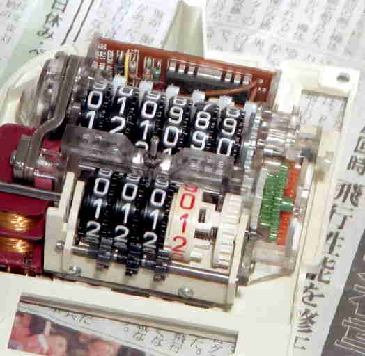 You
will need to remove the speedo needle and face to get this view. The
larger green wheel is what drives the trip meter. If you have sloppy
wheels, some people have shimmed them tighter. But, the large
translucent plastic screw you see on the far right is used to adjust the
end play of the main odometer gears. It might allow one to tighten up
wheels that have some wear and are not working if it's tightened to take
up play on the main shaft.
You
will need to remove the speedo needle and face to get this view. The
larger green wheel is what drives the trip meter. If you have sloppy
wheels, some people have shimmed them tighter. But, the large
translucent plastic screw you see on the far right is used to adjust the
end play of the main odometer gears. It might allow one to tighten up
wheels that have some wear and are not working if it's tightened to take
up play on the main shaft.