

Some while back, I had a
fuel sending unit on my K100 fail on me. It would not
register the volume at all. I had a chance to look at the
failing fuel level sender and discovered information that
would be useful for the community.
How does
the fuel sender work:
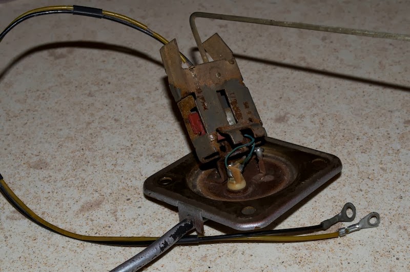
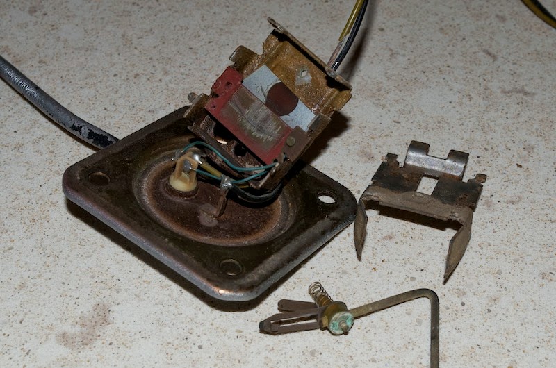
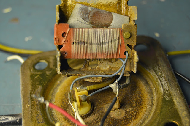
The sender has a movable arm ending in a float that raises
and lowers according to the fuel level. The arm articulates
a pair of metal wipers over two circuit cards. The assembly
is housed in a metal box welded to a bracket that mounts to
the bottom of the tank. The wiring goes through a
liquid-tight connector assembly.
Fuel
Level Sensing:
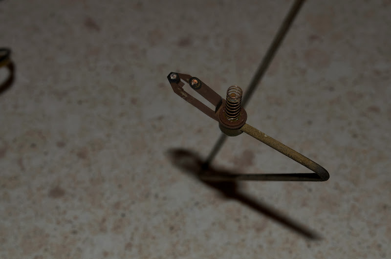
The float assembly arm has two electrical wipers attached to
it. The upper wiper sweeps across a 130 ohm wire wound
resistor plate, one end of which is connected to the
liquid-tight connector and the other end is not connected to
anything. The upper wiper outputs a variable resistance
value between 2 and 130 ohms, proportional to the position
of the wiper.
When the tank is full of fuel, the float is in its highest
position and the resistance measured should be around 2
ohms. When the tank is nearly empty, the float is at its
lowest position and the resistance measured should be around
130 ohms.
NOTE The fuel sender works in reverse to most modern motorcycle fuel senders, making it incompatible with many aftermarket gauges. This behaviour can be changed and will be described in a section below
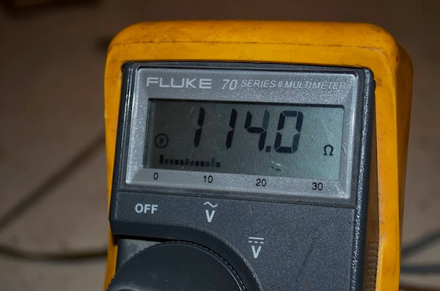
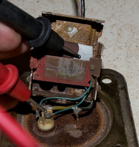
How to
Test the Fuel Level Sensing:
To test the resistive wire, use a multimeter with resistance
measuring capability. As in the photo set below, when
measuring between the connector and the left side of the
resistor, the value should be around 130 ohms.
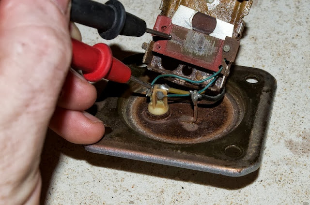
When measuring between the connector and right side of the
resistor, the value should be around 2 ohms.


How to
Recondition a Failing Sender:
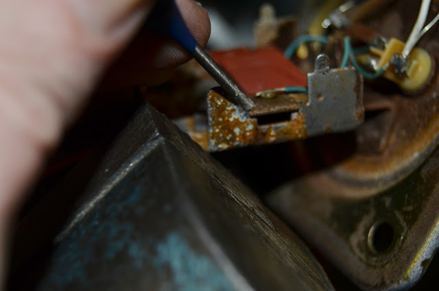
The sender tends to fail because years of accumulated
corrosion prevents electrical conductivity. The symptom of
corrosion will be erratic resistance readings from the upper
wiper and, most obviously, the fuel gauge will not register
anything on its display. In the photo below, note the thick
brown corrosion on the pivot hole and green corrosion on the
float arm pivot. All this corrosion prevents an accurate
resistance measure being sent to the fuel gauge. To
recondition a failing sender, it is necessary to open the
metal box and clean the contacts.
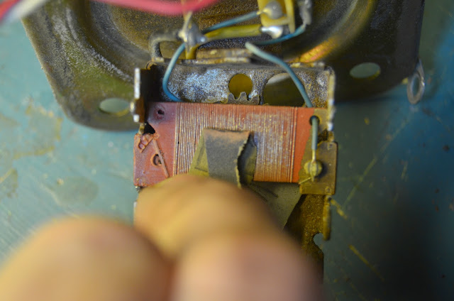
There are four tabs that hold the case closed. Carefully
bend the tabs straight and the top will separate. Be
careful because there is a spring under the wiper arm and it
may fly off.
Remove the wiper arm and check that the contact pads look
clean and shiny.
Depending on the age of the sender and other factors, it may
take no more than some Deoxit cleaner and a cotton swab to
clean the corrosion from the wires. I would try this first.
If the Deoxit doesn't get rid of the accumulated corrosion,
resort to a mildly abrasive paper. Using a small piece of
1200 grit wet and dry sandpaper, carefully clean the
resistive wires of accumulated corrosion. The technique is
to fold a tiny piece in half so that is has some stiffness
and careful drag it across the wires IN THE SAME DIRECTION
AS THE WIRES ARE WOUND. I use emphasis because you don't
want to drag the abrasive paper across the wires as it may
break them. Don't use any more pressure than is offered by
the stiffness of the sandpaper, such as pressing with your
finger. The wire used is very brittle and can easily break.
Using the same 1200 grit wet and dry, clean in and around
both pivot holes as well as the float arm pivots. It is
important to clean all corrosion from the pivots as from the
hub where the wiper blades are fixed. The spring is there
to act as a conductor, to allow electricity to flow through
the wipers, through the spring, through the pivots to
ground. This is the critical area where corrosion buildup
will break the sender. Once all corrosion is removed,
reassemble the parts.

Test whether the cleaning is successful by measuring the
resistance over the entire sweep of the float arm. The ohm
meter should read consistent increasing resistance as the
arm moves from full limit to empty limit.
Reserve
level Sensing:
The lower wiper on the float assembly arm sweeps across
another plate containing two circular contacts, one of which
is wired to the liquid-tight connector, the other is not
connected at all. The lower wiper outputs a binary signal
-- open circuit or grounded -- that communicates the reserve
volume to the low fuel light on the instrument cluster.
Normally, when the tank is full of fuel, the circuit is
open. When the arm reaches a certain position, the wiper
contacts the conductor and the output gets grounded. This
signals when the float reached the reserve position and the
instrument light should illuminate.
Testing
the Fuel Reserve:
To test, , use a multimeter with resistance measuring
capability. As in the photo set below, there should be
conductivity between the connector and the left side
plate.
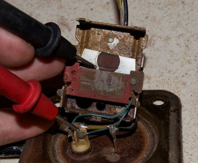
There should be no conductivity between that same conductor
and the right side plate.
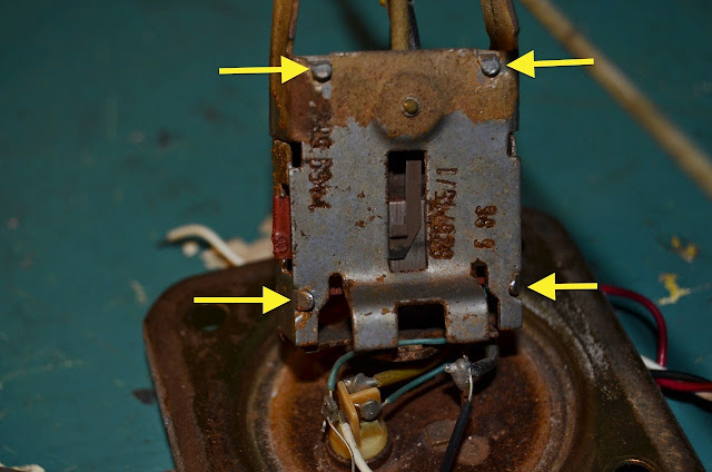
How to
Adjust the Reserve Level
Many people would think that one would have to bend the
float assembly arm to adjust the level of fuel where the
reserve light illuminates. Not so with the BMW fuel sender.
It has a built-in adjustment. The point where the low fuel
light illuminates is dependent on the point during the
rotation of the lower wiper when it encounters the contact
plate. There is an adjustment on the sender which can
determine when the lower wiper contacts the plate.
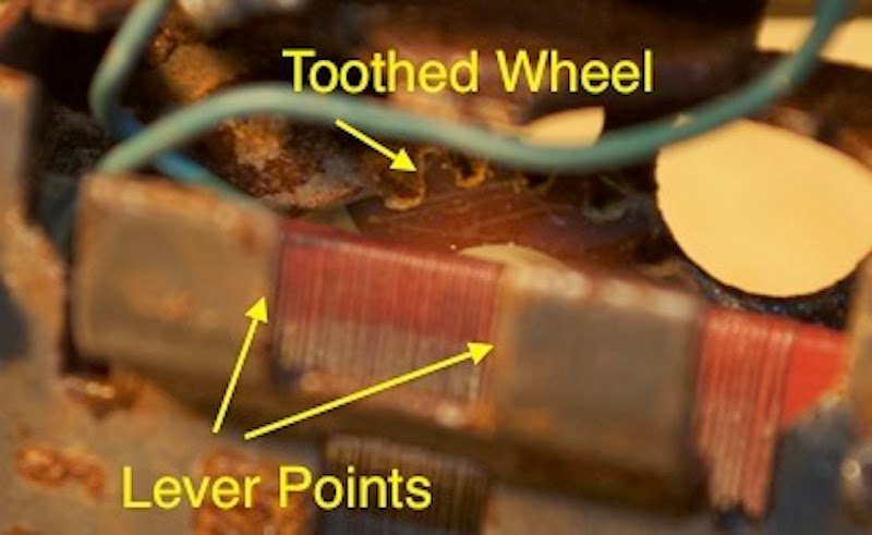
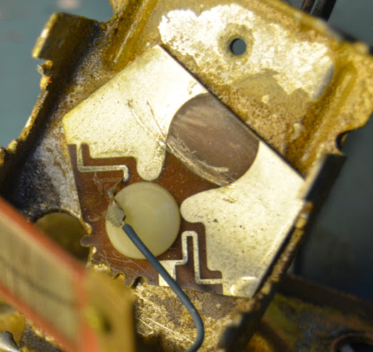
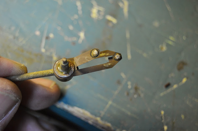
In the photo above, you can see a toothed wheel. This wheel
rotates on a nylon pivot, causing the bottom plate to be
rotated and the contact to change position. Using a small
screwdriver, get a purchase on either of the indicated lever
points and engage the tip of the screwdriver's blade with
one of the teeth of the wheel. Rotate the wheel with a
levering action.
-
Rotating the wheel CLOCKWISE will cause the wiper to contact earlier, resulting in a LARGER reserve volume.
-
Rotating the wheel COUNTERCLOCKWISE will cause the wiper to contact later, resulting in a SMALLER reserve volume.
How to
Modify the Fuel Sender to Make it Compatible with Modern
Gauges
As mentioned earlier, the fuel sender is incompatible with
modern gauges and aftermarket instrument clusters, like the
Koso, Dakota Digital and Acewell. It is a simple job to
modify the BMW fuel sender to make it fully compatible.
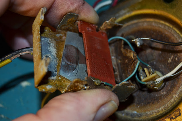
Disassemble the case by carefully straightening the four
tabs that hold the top with pliers until the top plate is
released.
Remove the top plate, float assembly arm and tension spring.
Be careful not to loose the spring nor damage the wipers on
the float arm. The resistor board will be revealed.
Locate the small tabs that secure the card to the frame.
These need to be moved out of the way to release the board
from the frame. I found that a set of slip-joint pliers
works best because they exert strong pressure and will not
slip. The tabs are very stiff so be careful not to bend
them too far nor break them. It will only be necessary to
bend the top two tabs a small amount to release their grip
on the resistor board.


Once the board is freed from the frame, carefully remove it
and flip it 180° so that the obverse side is now facing up.
Reinsert it back into the frame and close the tabs to
secure the board. Try to handle the board by its edges so
as not to touch the resistive wires. The board only goes in
one way so it's not possible to incorrectly orient the
board.
I found that using a small drift and hammer worked very well
for closing the metal tabs. You'll want the board to be
fully seated in the frame.

Before reassembling the frame, it is necessary to remove the
enamel coating from the resistive wires. Be very careful
with this operation so as not to destroy the brittle wires.
Using a piece of 600 grit Wet-n-Dry, lightly sand the wires
ONLY in the direction they are wound. If possible use a
multimeter set on resistance mode to test that the coating
is fully removed and there is conductivity. If you skip
this step or do not remove all the coating, the fuel gauge
will not work.
It's also a good time to clean up any corrosion on the wiper
tips and pivot.
Reassemble the sender by reinserting the float assembly arm,
spring and top plate. Form back the tabs that secure the
top using slip-joint pliers.

Once this operation is complete, electrically test the
sender. Use a multimeter set on a range that can measure
resistance between 1 Ohm and 200 Ohms. Place one probe on
the frame and the other on the white wire. When you move
the float assembly arm, the resistance should change between
these values. You will find that the resistance will now be
about 2 Ohms with no fuel and about 130 Ohms with a full
tank. This range is directly compatible with modern
Japanese and European gauges. You might need to program the
gauge to understand the sender's range.